

Mr Bacchus
Spa-Francorchamps
- Joined
- 26 Oct 2012
- Messages
- 303
After spending many many hours troubleshooting an ABS/PDAS warning light issue that I finally traced to a problematic longitudinal accelerometer I thought I would share my experience of testing the accelerometer.
Its a bit wordy but hopefully this can help others.
Problem: ABS and PDAS warning lamps illuminated plus 16 alarm bleeps. 99% of the time the lamps did not go out when engine is started but in some rare cases I could drive for a while but eventually the lamps would come on. Most recently the Brake Pressure warning lamp also decided to join the party.
Cause: Short or open circuit on the circuit board of the accelerometer (meaning sometimes it was going open circuit and sometimes going short circuit)
Solution: These sensors are not cheap to replace, I was quoted £???? by my local OPC and second hand sensors can be found on auction sites at the time of this post for about £150. I quickly discovered that just tapping the sensor could switch it between working and open circuit or short circuit so I deduced that my problem was a bad connection somewhere on the circuit board. I proved this by removing the screws that hold the board to the plastic housing and very gently lifting it, sure enough I could 'switch' the board between working and not working. I fiddled on for a while and quite by chance, by pressing quite hard on a solder joint with the point of screwdriver, I got the board to work correctly continuously. I appreciate this is not a permanent solution so I will have one of my suppliers, who makes printed circuit boards, make a permanent repair. I needed mine sorting ASAP as my MOT had expired last week and these lamps illuminated are a sure fail.
It is probably worth me trying to explain how these sensors work, although the Adrian Streather book and Porsche Workshop Manual provided my knowledge. The 964 has two identical accelerometers, located at 90 degrees to each other just forward of the gear stick under the carpeted cover. One accelerometer measures forward acceleration/deceleration (longitudinal sensor) and the other measures side acceleration (lateral sensor). The sensor has three contacts (I'm calling them pins), pin 3 receives 5 volts from the ABS/PDAS controller and pin 1 is the ground. Pin 2 provides an output voltage to the control unit of 2.7V when the car is on level ground. When the car is accelerating/decelerating the sensor will give an output of >2.7V or <2.7V depending upon its attitude.
During troubleshooting with the car on level ground I was getting either 5V or 0V out of pin 2, therefore the sensor was either open circuiting or short circuiting. I hit lucky during testing as I managed at one point to measure 2.7V and sure enough my lamps went out when the engine started. I removed the sensor from the car for further testing on the bench.
Here are some photos which hopefully help demonstrate my testing.
Photo below shows the measurement of 2.7V i.e. correct. Measured between pin 2 (by back-probing at the connector) and ground. If you measure between 1 and ground you get 5V, 3 and ground you get 0V. This is measured with ignition on, no need to start the engine.
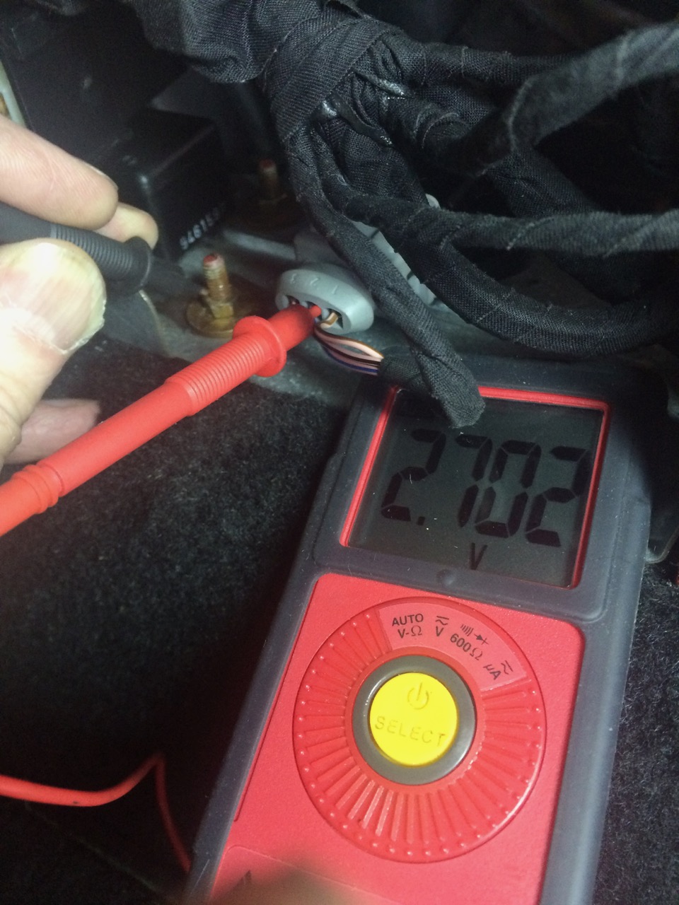
Photo below shows the pin numbers are marked on the connector moulding.
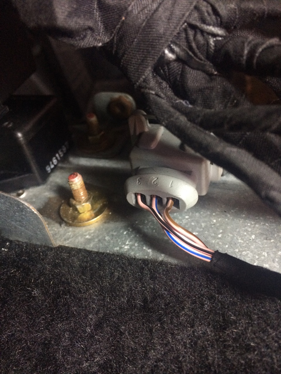
Photo below shows my bench testing kit: a power source set to output 5V, multimeter and some leads. The 5V was connected to pin 3 and the ground to pin 1.
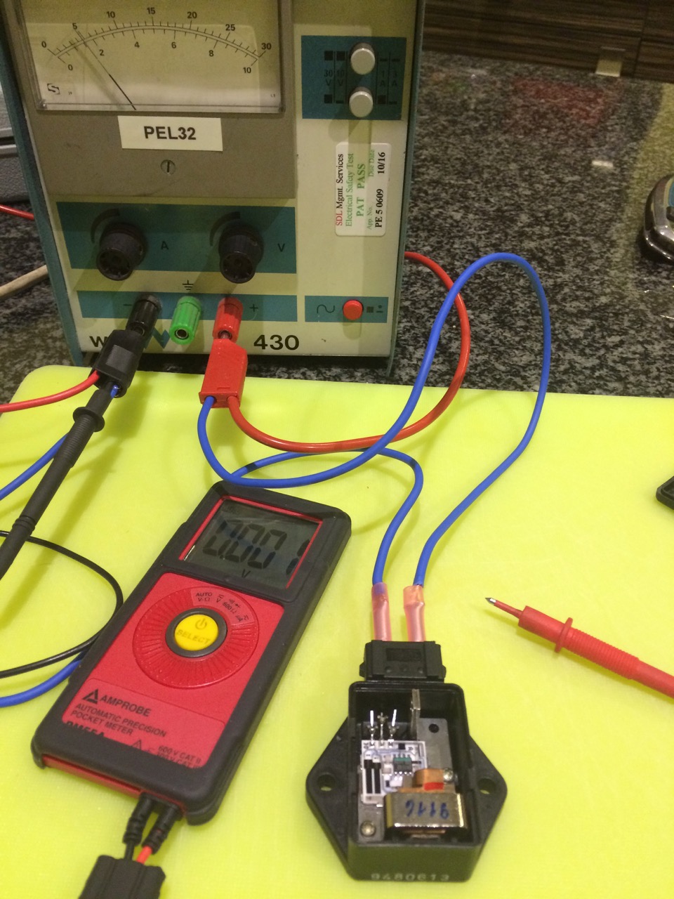
Photo below shows internals of sensor and the external and internal pins marked 1, 2, 3. The board connects to the 'Y' shaped connections that come through the moulding from external to internal.
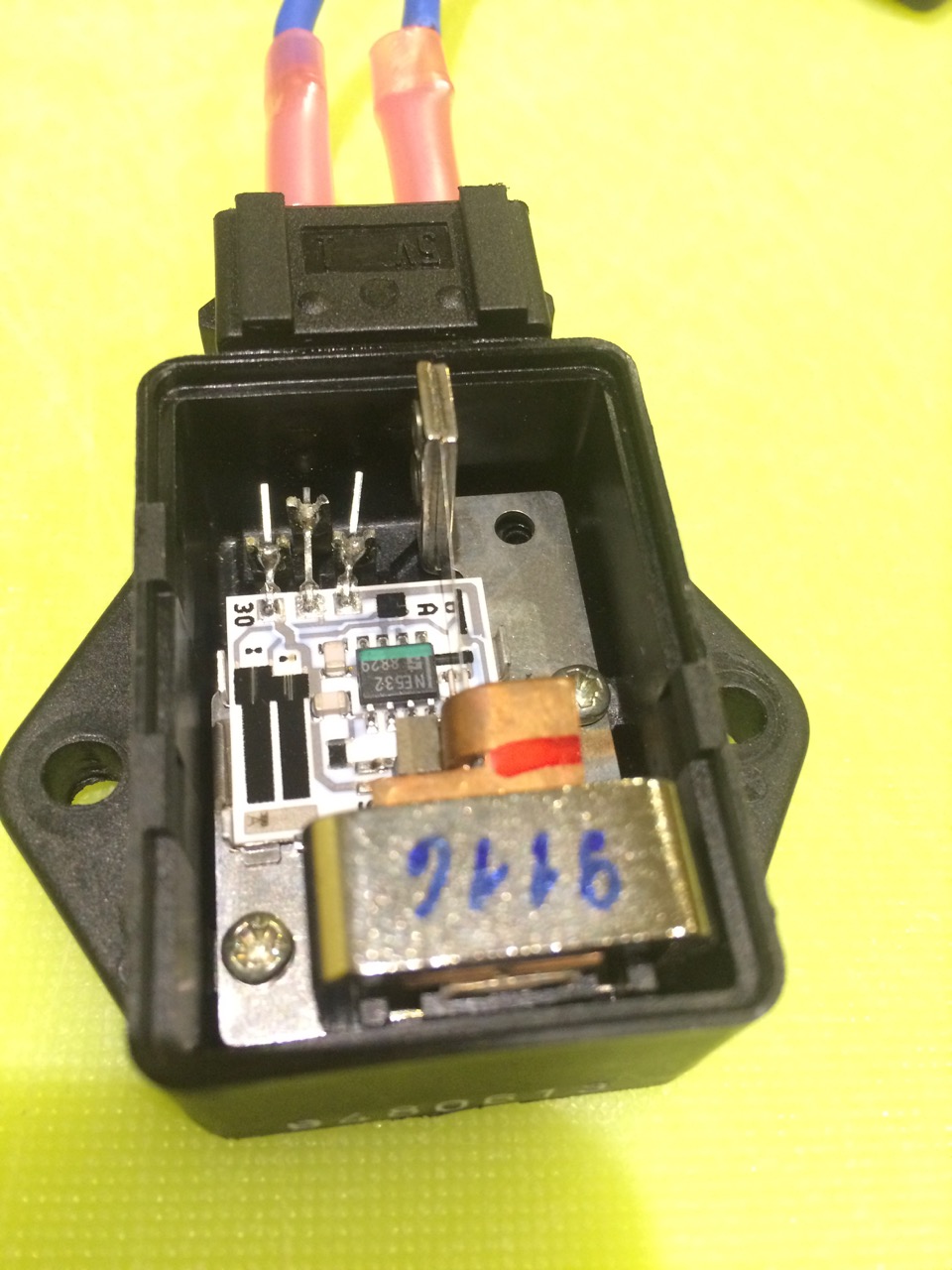
Photo below shows the measurement of 5V at pin 3. I'm actually probing at the connection to the board on the inside for ease of access, I had already checked continuity between the external and internal connections.
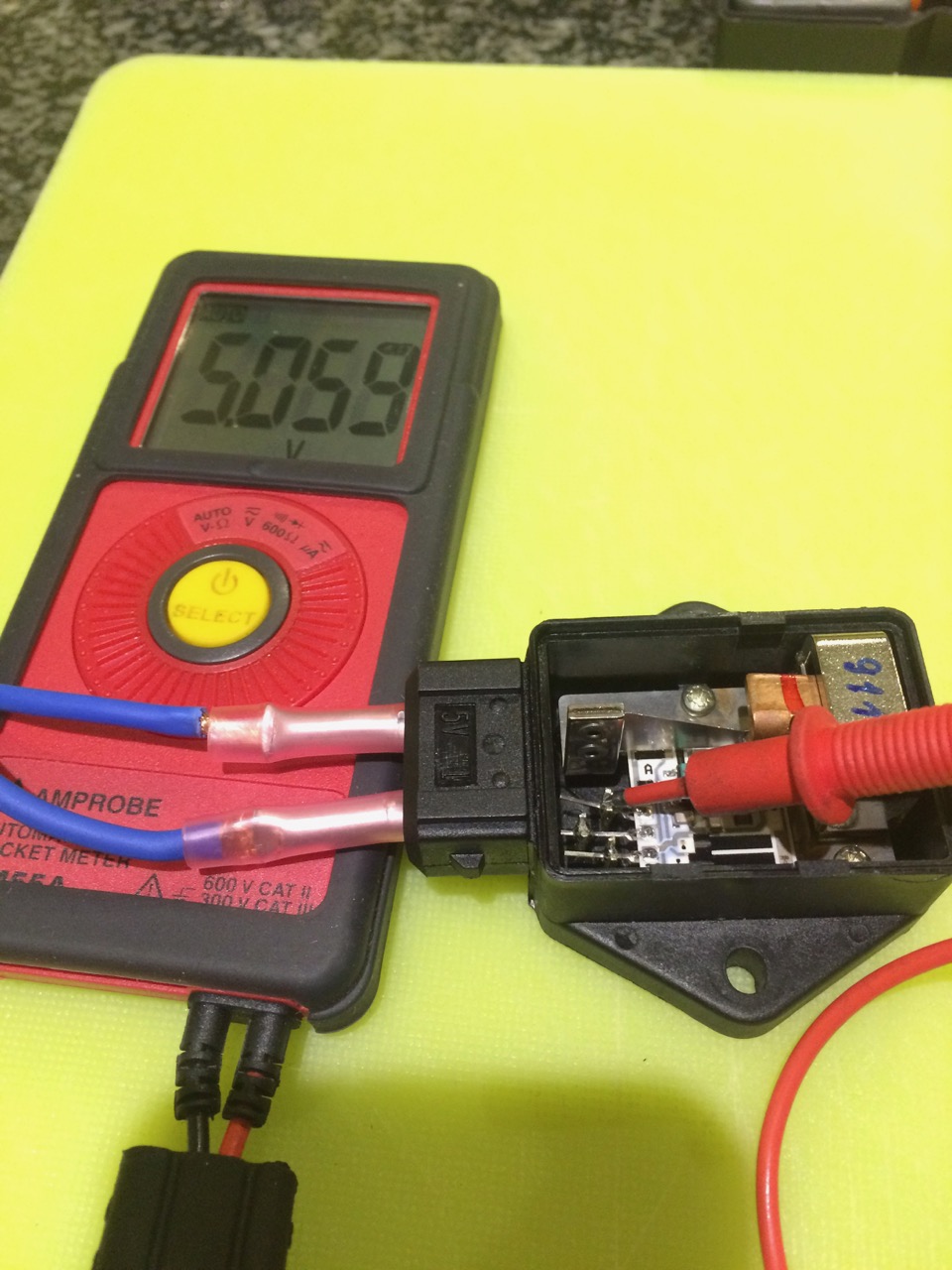
Photo below shows the measurement of 0V at pin 1.
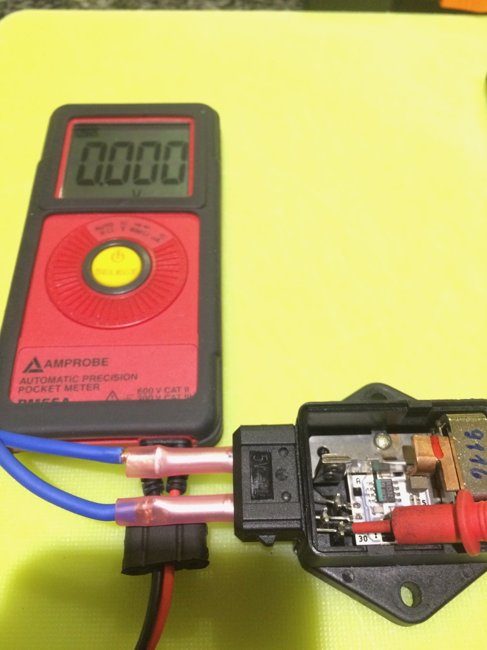
Photo below shows the correct measurement of 2.7V at pin 2 when the sensor is level.
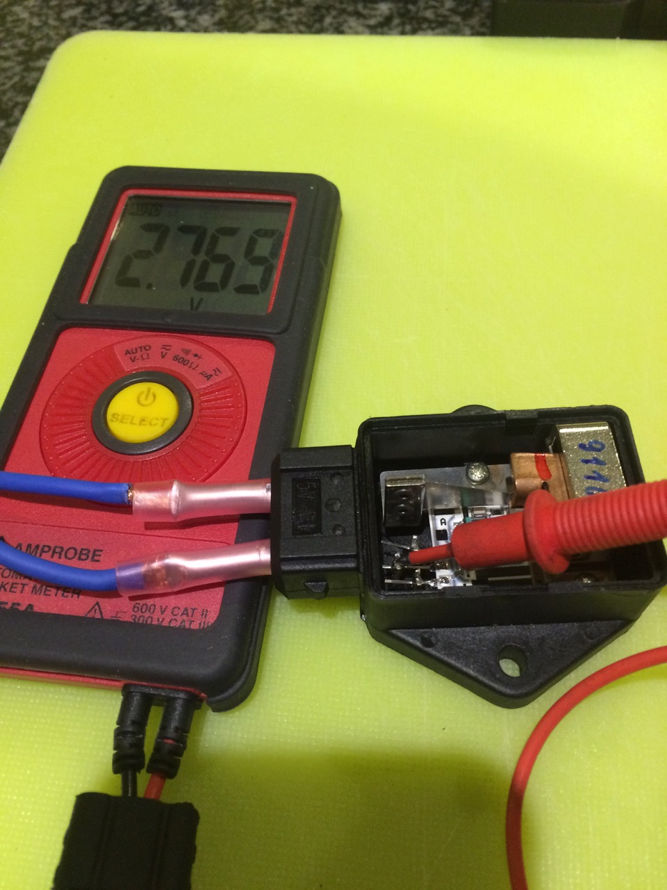
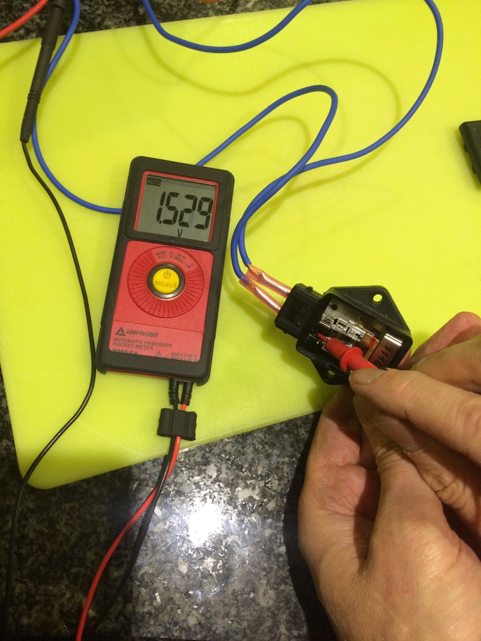
Photo below shows the measurement of > 2.7V when the sensor leans to one side.
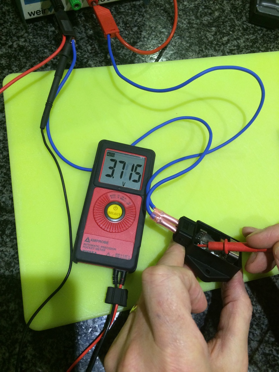
Photo below shows the measurement of < 2.7V when the sensor leans to the opposite side
Its a bit wordy but hopefully this can help others.
Problem: ABS and PDAS warning lamps illuminated plus 16 alarm bleeps. 99% of the time the lamps did not go out when engine is started but in some rare cases I could drive for a while but eventually the lamps would come on. Most recently the Brake Pressure warning lamp also decided to join the party.
Cause: Short or open circuit on the circuit board of the accelerometer (meaning sometimes it was going open circuit and sometimes going short circuit)
Solution: These sensors are not cheap to replace, I was quoted £???? by my local OPC and second hand sensors can be found on auction sites at the time of this post for about £150. I quickly discovered that just tapping the sensor could switch it between working and open circuit or short circuit so I deduced that my problem was a bad connection somewhere on the circuit board. I proved this by removing the screws that hold the board to the plastic housing and very gently lifting it, sure enough I could 'switch' the board between working and not working. I fiddled on for a while and quite by chance, by pressing quite hard on a solder joint with the point of screwdriver, I got the board to work correctly continuously. I appreciate this is not a permanent solution so I will have one of my suppliers, who makes printed circuit boards, make a permanent repair. I needed mine sorting ASAP as my MOT had expired last week and these lamps illuminated are a sure fail.
It is probably worth me trying to explain how these sensors work, although the Adrian Streather book and Porsche Workshop Manual provided my knowledge. The 964 has two identical accelerometers, located at 90 degrees to each other just forward of the gear stick under the carpeted cover. One accelerometer measures forward acceleration/deceleration (longitudinal sensor) and the other measures side acceleration (lateral sensor). The sensor has three contacts (I'm calling them pins), pin 3 receives 5 volts from the ABS/PDAS controller and pin 1 is the ground. Pin 2 provides an output voltage to the control unit of 2.7V when the car is on level ground. When the car is accelerating/decelerating the sensor will give an output of >2.7V or <2.7V depending upon its attitude.
During troubleshooting with the car on level ground I was getting either 5V or 0V out of pin 2, therefore the sensor was either open circuiting or short circuiting. I hit lucky during testing as I managed at one point to measure 2.7V and sure enough my lamps went out when the engine started. I removed the sensor from the car for further testing on the bench.
Here are some photos which hopefully help demonstrate my testing.
Photo below shows the measurement of 2.7V i.e. correct. Measured between pin 2 (by back-probing at the connector) and ground. If you measure between 1 and ground you get 5V, 3 and ground you get 0V. This is measured with ignition on, no need to start the engine.
Photo below shows the pin numbers are marked on the connector moulding.
Photo below shows my bench testing kit: a power source set to output 5V, multimeter and some leads. The 5V was connected to pin 3 and the ground to pin 1.
Photo below shows internals of sensor and the external and internal pins marked 1, 2, 3. The board connects to the 'Y' shaped connections that come through the moulding from external to internal.
Photo below shows the measurement of 5V at pin 3. I'm actually probing at the connection to the board on the inside for ease of access, I had already checked continuity between the external and internal connections.
Photo below shows the measurement of 0V at pin 1.
Photo below shows the correct measurement of 2.7V at pin 2 when the sensor is level.
Photo below shows the measurement of > 2.7V when the sensor leans to one side.
Photo below shows the measurement of < 2.7V when the sensor leans to the opposite side


")


